May 21, 2026
Blog
Machine Learning with Dynamics
Written by:
Most things that exist in the physical world are never truly static. They change over time, over space, or both. These ever-changing systems are said to exhibit dynamics. If you bend your idea of what computation is, anything with interesting dynamics can be used as a computer.
In this series, we gently introduce how to perform computation with dynamics by example. We will be using gyroscopes, springs, and rods to perform handwritten digit classification. There is no particular reason why these physical elements would make a good computer. In fact, this particular assembly of objects has likely never been used for computation. We chose it as it is simply a relatable system that is constructed from tangible objects which humans have some intuition about. We could have just as easily used jello, foam, magnets, or really anything else for this demonstration.
We will introduce our basic gyroscope-on-rod compute element and make a first attempt at completing the handwritten digit classification task. We will then increase the computational power of our system by introducing springs, and then complete the classification task.
Introducing Gyroscopes on Rods

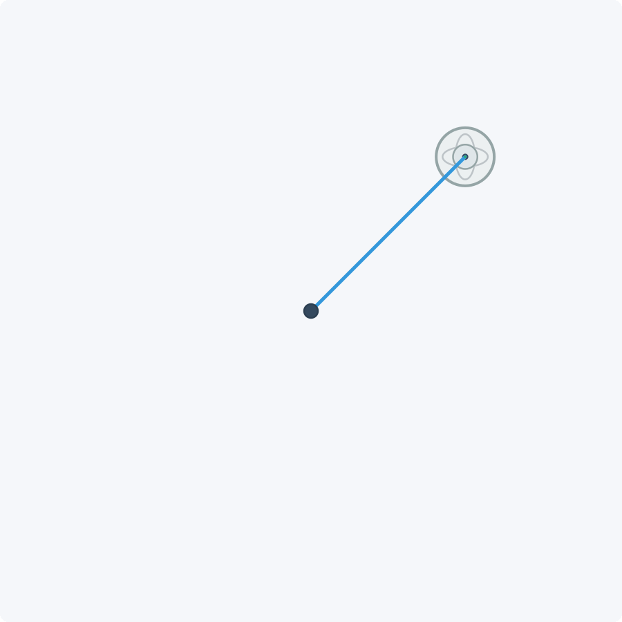
Top-down schematic of a gyroscope on a pendulum mount.
A gyroscope is a mechanical device used for maintaining orientation or angular velocity, and a rod is, well, a rod. If we affix a gyroscope to one end of a rod and affix the other end of the rod to a fixed surface, such as the ceiling, we create a pendulum with a gyroscope on the free end, suspended in air. The above visualization shows a top-down view of the gyroscope (grey circle) and the rod (blue line) with the mounting point (black dot) at the origin.
We will be using this gyroscope-on-rod system as a computer. When we perform computation with the dynamics of this system, we represent information with a property of the physical system. For the gyroscope, we will represent information using the x-y position and velocity of the gyroscope. When our gyroscope is at rest, it hangs underneath the anchor point of the pendulum and does not move. The usage of this computer works as follows:
- Applying Inputs – To feed inputs into the computer, we change the initial position and velocity of the gyroscopes, or nudge them over time. This embeds input information into the physical properties of the system.
- Computation – The gyroscope-on-rod system evolves over time, transforming the information encoded in the gyroscope position and velocity and thus performing computation.
- Reading Outputs – To read outputs from the computer, we measure the position and velocity of the gyroscopes after some time has elapsed.
Programming – To program the computer, we adjust the properties of the rod and gyroscope so that the system yields the desired dynamics.
Playing with the Gyroscope System
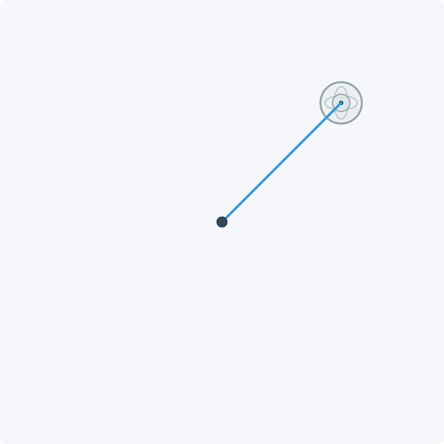
The gyroscope does not do anything interesting at rest. Let us say we now move the gyroscope from its resting position by ten degrees, release it, and then watch it move for 10 seconds. If we do this, the gyroscope moves through a transient and, if we were to wait long enough, it will settle toward a steady state, its resting position:
Evolution of the gyroscope-on-rod system over time.
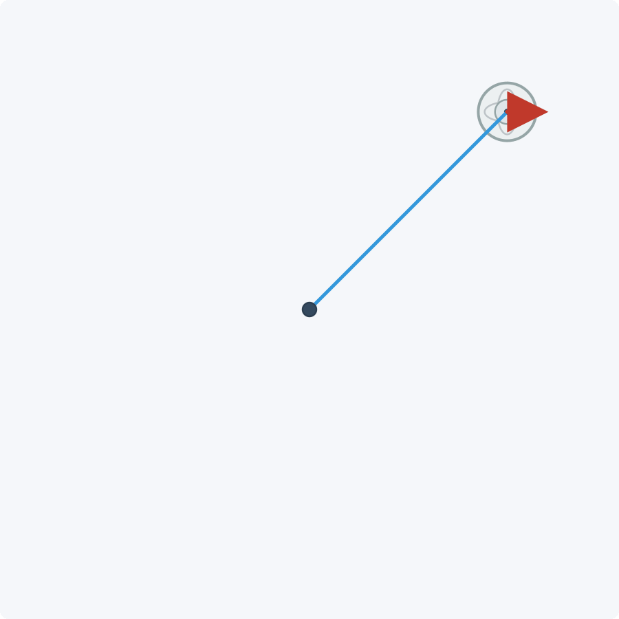
There are multiple ways to manipulate this gyroscope-on-rod to have interesting behavior. We may also push or pull the gyroscope as it is evolving to change its behavior. We can change the direction in which we push or pull the gyroscope over time to shape its movement:
 No external nudge |
 Slowly rotating nudge |
Both strategies can be used to encode inputs. We can apply inputs to our gyroscope-on-rod system to perform computation by setting the initial position of the gyroscope and nudging it over time.
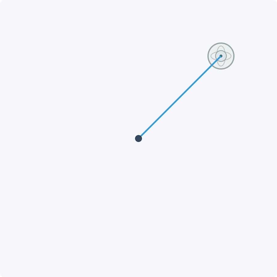
The dynamical system may be programmed by setting the length of the rod, the gyroscopic coefficient, and the mass of the gyroscope:
 Original Gyroscope-on-Rod System |
 2x Heavier Gyroscope |
 2x Longer Rod |
The above simulations all start from the same initial condition, but evolve differently due to differences in the gyroscope and rod. The heavier gyroscope moves more slowly, and the longer rod causes the gyroscope to move in a wider arc. If we continue with the computer analogy, we can say that the physical properties of the system are the “program” that we are running on the computer. We can change the program by changing the physical properties of the system. The nudges we apply to the gyroscope or the initial position of the gyroscope are the “inputs” to the program.
Take 1: Classification with Gyroscopes on Rods
Using the above gyroscope-on-rod dynamical system, we will next classify handwritten digits from their stroke trajectories. The PenDigits task in the time-series classification literature (AEON / timeseriesclassification.com) has 10 digit classes, and each example is a 100-step sequence with two input channels that track the x and y position of the digit.
This is a useful temporal sequence task because the same digit can be drawn in many different ways. A good classifier must keep the signal that makes a 5 recognizable as a 5 while forgetting the variations between different 5s. In other words, it must remember the signal and forget the noise.
 PenDigits dataset.
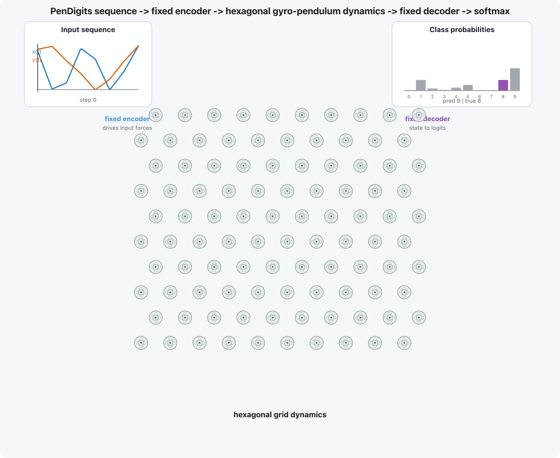
Classifier. The heart of the classifier architecture is a network of 100 gyroscopes organized into a 10×10 hexagonal grid with five input gyroscopes (left) and five output gyroscopes (right). In this classifier architecture, the stroke inputs are sequentially fed into a linear encoder that translates each stroke input into a set of x-y nudges to apply to the input gyroscopes. After the input sequence has been fed into the system and five seconds of gyroscope time have elapsed, the gyroscope velocities and positions are measured to produce a second embedding. This gyroscope-produced embedding is then translated to logits with a linear decoder, which are then normalized by a softmax into class probabilities:

Classifier layout: encoder → gyroroscope network → decoder / softmax
Training our Classifier. We train our combined neural network and gyroscope-on-rod system using standard training methods to perform the above digit classification task. In the neural network encoder/decoder, the trainable parameters are simply neural network weights. In the gyroscope system, the pendulum lengths, gyroscope masses, and gyroscopic coefficients are trainable parameters. We train the gyroscope and rod parameters to take on sane values. For example, the learned mass of the gyroscope should not be negative.
A Critical Flaw: We actually cannot train this gyroscope-on-rod system as written because the system dynamics have a critical flaw: the input gyroscopes cannot affect the output gyroscopes!
Evolution of gyroscope network in classifier
While each gyroscope has rich dynamics for self-interaction, there is actually no interaction between gyroscopes, so information cannot propagate through the gyroscope network. Without any sort of interaction between gyroscopes, we cannot train this system to perform the task.
Making Gyroscopes Talk to Each Other with Springs
As we saw in our first-take attempt, the current gyroscope-on-rod system doesn’t have any mechanism that allows for gyroscopes to influence one another. This training task is futile from the start, since the gyroscopes that were receiving the stroke input could not pass information to the hidden gyroscopes, or the output gyroscopes. So, we need gyroscopes to interact — what do we do? We can simply connect pairs of gyroscopes with springs! The spring will pull or push the gyroscopes together or apart, depending on the relative velocity of the two gyroscopes and the strength of the spring. This will allow the gyroscopes to influence one another, and pass information between them:
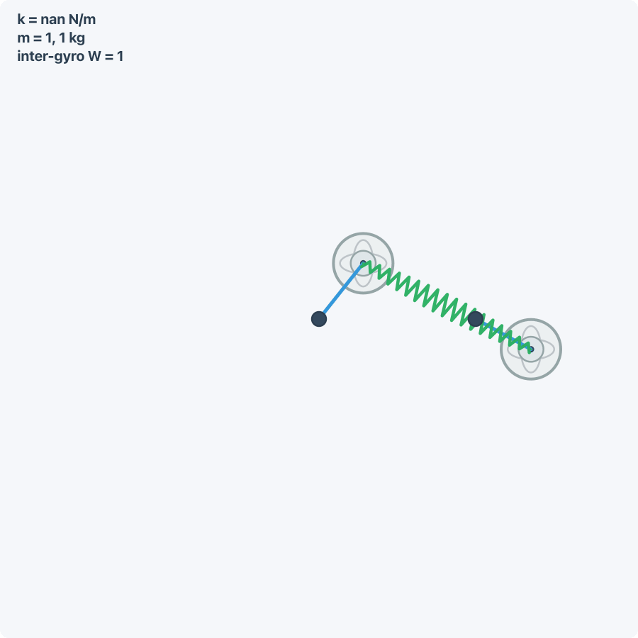
Two gyroscopes-on-rods connected with a spring.
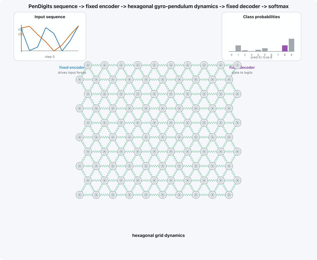
Take 2: Using Gyroscopes with Springs for Classification
We now use the same classifier architecture as before, but now the gyroscopes are interconnected by springs that have trainable coupling strengths. We arrange gyroscopes in a hexagonal grid where each gyroscope is connected to six of its neighbors. This gives us a total of 300 springs and 100 gyroscopes:
 Now that the gyroscopes can interact with one another, we can now train the system to perform classification. The system is then trained to minimize the cross-entropy loss of the PenDigits task with a time step of 0.05 seconds, 25 epochs, and batch size 32:

Training and validation metrics from a saved nonlinear PenDigits classifier run.
As training progresses, the classifier learns the task, achieving a validation accuracy of 0.834. For context, a linear classifier of similar complexity achieves 0.562 and an LSTM achieves 0.896 on the same task. So, even for this simple task, the physical system can learn it reasonably well.
We can also inspect the learned parameters to see how the system has learned the task. Visualized below are the learned mass, pendulum length, gyroscopic strength, and coupling strengths:
 Learned gyroscope masses, rod lengths, gyroscopic strengths, and coupling springs.
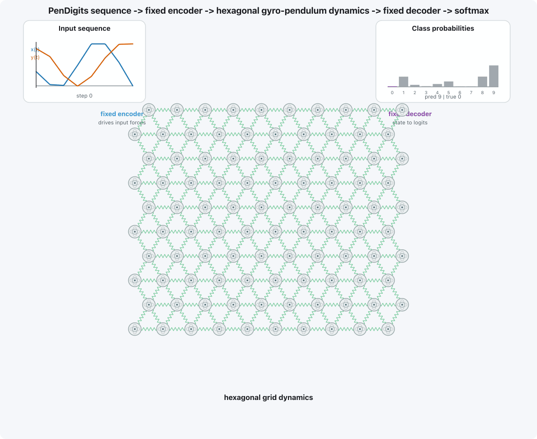
We can also simulate the system on an input sequence to see how the gyroscope+spring system performs the task. Here is the evolution of the gyroscope system as it correctly classifies a pen drawing of the digit 8 as it evolves over time:
 Visualization of the gyroscope+spring system as it correctly classifies a pen drawing of the 8 digit as it evolves over time.
Here is the system when supplied with an input with a ground truth label of zero:
Visualization of the gyroscope+spring system as it correctly classifies a pen drawing of the 0 digit as it evolves over time.
Though we train the system with a GPU, we can perform inference with the original gyroscope-and-spring physical system. When configured with the learned physical parameters, the gyroscope and spring system is able to correctly classify a written digit as the stroke evolves over time. This physical system we used as a demonstration was not chosen for any particular reason related to computation, it was simply a relatable system that is constructed from tangible elements which humans have some intuition about. As you might imagine, any physical system could be used in its place to perform computation. We’ve shown you can train such a system to perform computation, you may next be wondering how we train such a classifier.
Training the Gyroscope System: How it Works
We next go over the mechanics of training a system that incorporates physics. We can train both the neural network parameters and the gyroscope, spring, and rod properties in the classifier model using ordinary backpropagation. To be able to train the model, we need to be able to backpropagate through both the gyroscope-on-spring system’s dynamics to compute the parameter sensitivities and perform the gradient update. To accomplish this, we need a differentiable model of the dynamics of the gyroscope-on-spring system.
Differential equations are the logic of dynamics-based computation, and so we will formally describe the evolution of the gyroscope’s x-y position and x-y velocity with a system of ordinary differential equations (ODEs). Once we formulate the ODE model, we can backpropagate through the physics using differentiable ODE solvers reserved for training Neural ODEs.
Mathematically Modeling the Gyroscopes-on-Rods Computation
We first model the gyroscope system without springs. We will use (x,y) to denote the x-y position, (v_x, v_y) to denote the x-y velocity, (x_0, y_0) to denote the gyroscope’s resting position. The coordinates (\Delta x, \Delta y) will denote the gyroscope’s x-y position relative to its resting position:
The following system of ordinary differential equations describes how the gyroscope's x-y velocity evolves over time; the right hand side of the equation computes the acceleration of the gyroscope:
\dot{\mathbf{v}_{x}} = -\frac{g}{\sqrt{L^2 - (\Delta x^2 + \Delta y^2)}}\,\mathbf{\Delta x} - \frac{\gamma}{m}\,\mathbf{v_y} - \frac{c_{\text{damp}}}{m}\,\mathbf{v_x}\,\sqrt{\mathbf{v_x}^2 + \mathbf{v_y}^2} + \frac{\mathbf{f}_x(t)}{m} \dot{\mathbf{v}_{y}} = -\frac{g}{\sqrt{L^2 - (x^2 + y^2)}}\,\mathbf{y} + \frac{\gamma}{m}\,\mathbf{v_x} - \frac{c_{\text{damp}}}{m}\,\mathbf{v_y}\,\sqrt{\mathbf{v_x}^2 + \mathbf{v_y}^2} + \frac{\mathbf{f}_y(t)}{m}The first term is the gravitational force pulling the gyroscope down, the second term is the gyroscopic force pulling the gyroscope in the direction of its velocity, the third term is the air resistance force pulling the gyroscope in the opposite direction of its velocity, and the fourth term is the force we apply to nudge the gyroscope in the x and y directions as it evolves.
The x-y position of the gyroscope is simply the integral of its velocity over time:
\dot{\mathbf{x}} = \mathbf{v_{x}}, \qquad \dot{\mathbf{y}} = \mathbf{v_{y}}.Parameters: The parameters in the model correspond to the physical properties of the system. The parameter m is the mass of the gyroscope, the parameter L is the length of the rod, and the parameter \gamma is the gyroscopic coefficient. There are, of course, constraints on these parameters to ensure they are physically plausible. For example, the length of the rod and the mass of the gyroscope must both be positive. The damping cdamp and g parameters are physical constants that cannot be changed.
Inputs: The inputs are applied to the system by setting the original state of the gyroscope, or by nudging the gyroscope over time:
- To start the gyroscope at a specific
xandyposition, we set the initial conditions x(0) andy(0). In this setting, we set the initial velocity to zero (v_x(0)=v_y(0)=0) since it is hard to initialize. - To apply nudges to the system, we set the functions
f_x(t)andf_y(t)to time-varying functions that control the amplitude of the force in the x and y directions.
For the original gyroscope-on-rod system we observed in the cartoon, the position and velocity of the gyroscope evolves as follows:

Timeseries plot of single gyroscope’s velocity and position over time.
Modeling Interconnected Gyroscopes-on-Rods with Springs
To incorporate the physics of spring connections into our original gyroscope-on-rod dynamical system, we introduce an interaction term into the differential equations that models this coupling behavior.
For a network, let (x_i^0,y_i^0) be the resting position of gyroscope i on the network when no springs are used. The pendulum restoring force depends on displacement from rest, (x_i-x_i^0, y_i-y_i^0). For a coupling spring between gyroscopes i and j, we define the distance between gyroscopes with d_{i,j} and the distance between resting positions with l_{i,j}:
\begin{aligned} d_{ij} &= \sqrt{(x_j-x_i)^2 + (y_j-y_i)^2}, \\ \ell_{ij} &= \sqrt{(x_j^0-x_i^0)^2 + (y_j^0-y_i^0)^2}. \end{aligned}The equations below model the evolution of gyroscope i in a system of (1..j..N) gyroscopes with interconnected springs:
\small \dot{v}_{x,i} = -\frac{g(x_i-x_i^0)}{\sqrt{L_i^2 - ((x_i-x_i^0)^2 + (y_i-y_i^0)^2)}} - \frac{\gamma_i}{m_i}v_{y,i} - \frac{c_{\text{damp}}}{m_i}v_{x,i}\sqrt{v_{x,i}^2 + v_{y,i}^2} + \frac{f_{x,i}(t)}{m_i} + \underbrace{\frac{1}{m_i}\sum_{j \in \mathcal{N}(i)} K_{ij}(d_{ij}-\ell_{ij})\frac{x_j-x_i}{d_{ij}}}_{\text{inter-gyro coupling}} \small \dot{v}_{y,i} = -\frac{g(y_i-y_i^0)}{\sqrt{L_i^2 - ((x_i-x_i^0)^2 + (y_i-y_i^0)^2)}} + \frac{\gamma_i}{m_i}v_{x,i} - \frac{c_{\text{damp}}}{m_i}v_{y,i}\sqrt{v_{x,i}^2 + v_{y,i}^2} + \frac{f_{y,i}(t)}{m_i} + \underbrace{\frac{1}{m_i}\sum_{j \in \mathcal{N}(i)} K_{ij}(d_{ij}-\ell_{ij})\frac{y_j-y_i}{d_{ij}}}_{\text{inter-gyro coupling}} \dot{\mathbf{x}} = \mathbf{v_{x}}, \qquad \dot{\mathbf{y}} = \mathbf{v_{y}}.The parameter K_{i,j} captures the stiffness of the spring connecting gyroscopes i and j, and the coupling term captures the effect of the spring coupling on the gyroscope i's velocity. The force on gyroscope i points along (x_j-x_i, y_j-y_i), so a stretched spring (d_{ij} > \ell_{ij}) pulls i toward j, while a compressed spring pushes it away. Now, armed with a physical behavior that enables gyroscopes to influence one another, we can train the system to perform the task!
Here is the inference run for digit classification, but now plotted as a time-series of gyroscope positions and velocities:

The x-axis plots the time elapsed, in seconds, and the y-axis plots the velocity and position of the gyroscopes in the system.
Performing Inference
For inference, we can of course use actual gyroscopes, rods, and springs to run the computation. However, if we don’t want to carry gyroscopes and springs around to perform computation, there are other more practical options:
ODE Simulation. The trajectories can be solved classically with a differential-equation solver, such as RK4, which sequentially time steps the system forward in time using the ODE system. Because this ODE system is non-linear, there is no closed-form solution for the trajectories, so there is no shortcut for computing the measurement from the input configuration. Here, run time \propto time steps \propto difficulty of the ODE simulation task.
Emulation. We can build another physical system, such as an electrical circuit, that emulates the dynamics of this system. This physical emulator encodes information with different signals and signal properties, but has dynamics that match the gyroscope system. With emulation, we use the same execution process as with the original gyroscope system, but with voltages and currents. With physical emulators, there is a straightforward linear mapping between gyroscope time and emulator time – for example, 1 second of gyroscope time maps to 1 microsecond of circuit time. This means performance is predictable and known before the computation is actually executed.
Looking Forward: Beyond Gyroscopes
As we alluded to before, any physical system could be used in its place to perform computation. We can take this idea even further. If we are emulating or simulating a physical system for the purposes of performing machine learning, the actual implemented dynamics do not even need to be physically accurate to the original system.
For example, if our hardware surrogate can emulate the gyroscope system with negative mass, then we can train with negative mass to enhance the expressivity of the system – even though this does not make physical sense. Essentially, in this context, we are inspired but not constrained by the physical system. So, on top of the myriad of physical systems we can leverage for computation, there are an infinite number of ways we can bend the dynamics of these systems to improve their ability to do computation.